Folded Dipole Homemade Ham Radio Antenna
by Claude Jollet - VE2DPE
(N-D-Prairies, Québec, Canada)

Folded Dipole Diagram
NOTE: important corrections have been made on June 16, 2019 to the following text.
I have just put up a homemade ham radio antenna. It's a folded dipole for the 6 meter band. The construction technique can be applied to other bands.
It was so much fun to build and it works so well that I thought of sharing the details of my project here.
I have been itching to get on 6 meters for years for many reasons.
1. A 6 meter ham radio antenna is easy to build and it is small enough to fit almost on any property.
2. It's a "relatively difficult" band to work because of propagation. There is a challenge worthy of my attention up there! :-)
3. It is far from overcrowded, a welcome feature when compared with lower HF bands!
4. Even if the band is technically a legal ham radio band in Canada, it was off limits to me ... until very recently!
Why was the 6 meter band off limits to me?
We live in the deep fringe area of a popular TV channel 2 station (located about 60 km or roughly 40 miles away). I had to avoid going on "six" because I would have wiped out the very weak channel 2 TV signal in my neighbourhood, even on QRP (... I tried one night)! :-(
I finally got my chance to to get on six meters when Canada's TV stations switched over to digital. The station that was on channel 2 (on 54 MHz) moved up to channel 19 on 500 MHz). That was the event I was hoping for. Now, I could try my hand at at building a 6 meter ham radio antenna!
Why I Chose A Folded Dipole
The folded dipole has a slightly better SWR bandwidth than a conventional single wire dipole. In other words, a greater portion of the band is available at less than 1.5:1 SWR than with a single wire dipole.
While reading back on the folded dipole vs the single-wire dipole in the ARRL Antenna Handbook, I decided to feed my homemade with ladder line to minimize transmission line losses. This is very desirable for weak signal work on receive. I also want to try working "six" on QRP. Every decibel of signal strength counts on QRP!
I had enough ladder line to experiment with. From the formula for a half-wave dipole (468/f MHz) the antenna part would require about 9 feet 4 inches (2.83 meters). I will have to trim it to resonance.
I wanted the antenna to be at least one wavelength above ground to minimize ground effects. I would have liked it to be higher but I had to make do with the available antenna end supports:
1. a 24 foot TV tower in the back of the house,
2. my 48 foot ham radio tower about 30 feet away from the schack.
The TV tower height thus became the height limit I would have to work with. Thankfully, it was high enough.
No Tuner Needed
I also wanted to avoid using an antenna "tuner" to reduce the complexity of my first trials.
I may still build and use a tuner because I will be experimenting with homebuilt QRP rigs and/or modified equipment.
The tuner I have in mind will be a low-pass "L" network. It will help reduce possible emission of harmonics. Most TV stations have moved up and away from the lower frequency channels, but their signal strength hasn't, at least in my area!
Transmission Line
I needed about a 30 foot long feed line to cover the distance between my radio shack and the antenna. However, a coaxial transmission line can significantly reduce signal strength at 50 MHz, unless it is of the low loss variety. Proceeding by elimination, choosing the type of transmission line became easy, really.
1. Low loss 50 Ohm coax (i.e. RG-8 Belden 7810A) = much too heavy for the application (I have no center support for the dipole) + much too expensive for me + 4:1 balun would have to be at the antenna feed point and would further increase the weight load at the antenna feed point.
2. Smaller low loss 50 Ohm coax (i.e. RG-8X Belden 7808A) = expensive and still requires a balun at the antenna feed point (which I wanted to avoid for weight considerations).
Using the same ladder line for the transmission line that I use for the folded dipole became the obvious ideal choice:
1. a tolerable 1.5:1 impedance mismatch between antenna and line = means near maximum signal transfer (a folded dipole has a characteristic impedance around 300 ohms and my ladder line's characteristic impedance is 450 ohms).
2. ladder line has the lowest possible line loss of all transmission line types.
3. ladder line is the lightest of all types of transmission lines.
By the way, TV type 300 Ohm twin lead is very lossy, compared to open wire ladder line made of 16 gauge wire. Worse, the antenna part of the system would soon break under high winds or icing conditions. TV Twin Lead is simply not strong enough.
Coupling The Line To The Antenna
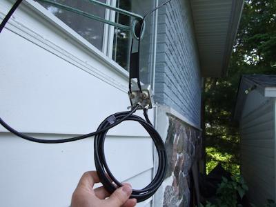
No balun is required at the antenna feed point because it is fed directly with ladder line. (see photo)
Coupling The Line To The Transceiver
A balun is required because ladder line is a balanced type (theoretical nominal impedance of approximately 450 Ohms) and the transceiver RF input/output is unbalanced 50 Ohm type.
In theory, a 9:1 step-down balun would be required between the 450 ohm ladder line and the 50 ohm coax lead in to the shack.
However, because of the impedance mismatch at the antenna connection to the feedline, I had no idea what the complex impedance would be at the other end of the ladder line.
I chose to try a 4:1 half wave coaxial balun for simplicity's sake (see photos). I got the idea from the ARRL Antenna Book (21st Edition, p.18-6).
I also chose to build the balun using RG-8X coax ... because I had enough in stock! ;-) (see photos).
Designing And Testing The Antenna System
I used a RigExpert Antenna Analyzer, model AA230-PRO to measure and test the half-wave 4:1 balun, the folded dipole antenna itself and the entire antenna system. (see video and photos)
Dimensions Of The Finished Antenna
You could do without a antenna analyzer if you build your six meter folded dipole antenna system with the following dimensions:
==> Six meter folded dipole made of 450 ohm ladder line, #16 7 strand copper clad steel wire : 8.66 feet (2.64 meters) long. Resonates at 50.4 MHz.
==> 4:1 coaxial balun, half wave at 50.4 MHz, made of RG-8X, 7.93 feet (2.417 meters long).
==> Transmission line made of 450 ohm ladder line (same as folded dipole antenna portion). Use whatever length you require. Mine is 30 feet long (9.144 meters).
Results
The finished antenna system is cut to resonate at 50.4 MHz and has an SWR of 1.19:1. It also has a fairly broadband response.
1.28:1 SWR at 50.0 MHz
1.19:1 SWR at 50.4 MHz
1.28:1 SWR at 51.0 MHz
Being mostly made of low loss ladder line (except for the RG-8X coaxial step down balun), it will be a very efficient antenna system.
Parts From The "junk box"
==> About 45 feet of ladder line (#16 7 strand copper clad steel) believed to have about 450 Ohm impedance (leftover from another project)
==> About 20 feet of RG-8X coax - used for the coaxial 4:1 balun and for transmission line between balun and transceiver.
==> A old TV 5-port splitter box as junction box for the connections transmission line - balun - lead in coax to the shack (see photos).
==> Three (3) "F" connectors (the type for TV connection cable).
==> one (1) PL-259 connector for the coax lead in to the shack.
About the only thing that I had in stock, but that didn't come out of my "junk box", is my love of tinkering with antennas! ;-)
73 de VE2DPE
Comments for Folded Dipole Homemade Ham Radio Antenna
|
||
|
||
|
||
|
||
|
||
73 de VE2DPE
Claude Jollet
104-30 avenue des Berges,
Notre-Dame-des-Prairies, Québec, Canada J6E 1M9
QTH Locator: FN36gb
Disclosure
If
you make a purchase via a link on this site, I may receive a small
commission on the transaction, at no extra cost to you. Thank you!
(One word queries work best)
FOUND THIS
SITE
USEFUL?
VE2DPE
Is a member
in good standing
of


Also a proud member of an international community of solopreneurs
using SoloBuildIt!
(SBI!)
to promote my self-published eBooks
since 2005.
See my review
of this unique product for online businesses.
CQ CQ CQ
If you have a question, a comment or a topic you would like me to cover, please do not hesitate to ask here.


