The Off-Center-Fed Dipole
(OCFD)
Understanding How It Works
Can Pay Off
I like the off-center-fed dipole (OCFD) because it performs quite well on most amateur radio frequency bands... if you are not afraid to stray away from the "traditional" way of doing things.
Before going any further, I should mention here that the OCFD is sometimes falsely referred to as a "windom" antenna.
- A windom antenna is a single-wire-fed antenna which is worked against
ground.
It's a grounded vertical wire connected to a horizontal portion acting as a top hat capacitance. - On the other hand, an OCF dipole is an ungrounded dipole antenna fed with twin-conductor line, either coaxial or open wire parallel conductors.
The so-called "OCF windom" is also a misnomer, for the same reasons.
Recall...
A half-wave dipole is usually fed at its center because this is where maximum current occurs. Feeding the dipole at that point yields a minimum (free space) impedance of 70-72 ohms. This makes it possible to use the popular 50 ohms coaxial with relatively low mismatch SWR levels... on the fundamental frequency and odd harmonics thereof (ex. a 7MHz half-wave dipole will also work on 21 MHz).
But keep in mind that the impedance of a half-wave dipole varies with height above ground. For example, when it's installed at a height of 0.13 wavelengths above average ground, its impedance will be closer to 50 ohms which is perfect for 50 ohms coaxial line.
The Harsh Reality
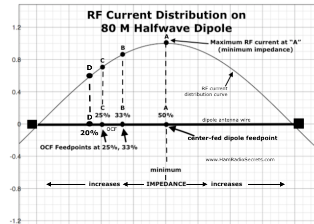
The impedance of a half-wave dipole rises as we move the feedpoint off-centre - away from maximum RF current (minimum impedance of 70-72 ohms)... and into increasing RF voltage territory.
Manufacturers of off-center-fed dipole antennas choose an offset feedpoint where the theoretical impedance is approximately 300 ohms on the antenna's *fundamental* frequency of resonance. They will then be able to use a 6:1 current balun (RF choke) at the feedpoint which will conveniently allow the use of 50 ohm coax... which most ham radio operators like to use. This convenient feedpoint impedance is located about 1/3 (33%) of the dipole length away from one end.
- But, remember that a dipole's feedpoint impedance will vary with its height above ground, and with the dielectric constant of the ground below the antenna. Therefore, the 6:1 balun will likely be transforming impedances lower than 300 ohms... which makes the impedance-transforming ratio unpredictable. In such a case, the current balun will only serve as a RF choke… which is better than nothing, I guess.
- Also, please note here that this "neat" 6:1 arrangement falls to pieces as you try to use the same OCF antenna on other frequency bands than the fundamental frequency for which it was intended. The impedance will *not* be 300 ohms on the other frequency bands - the main reason behind using an OCFD.
Off-center-fed dipole (OCFD) Guiding Principle
If there is RF current present at the chosen offset feedpoint of an 80 M half-wave off-centre-fed dipole (OCFD), then this feedpoint is "usable".
But, is it the best feedpoint position for multiband use?
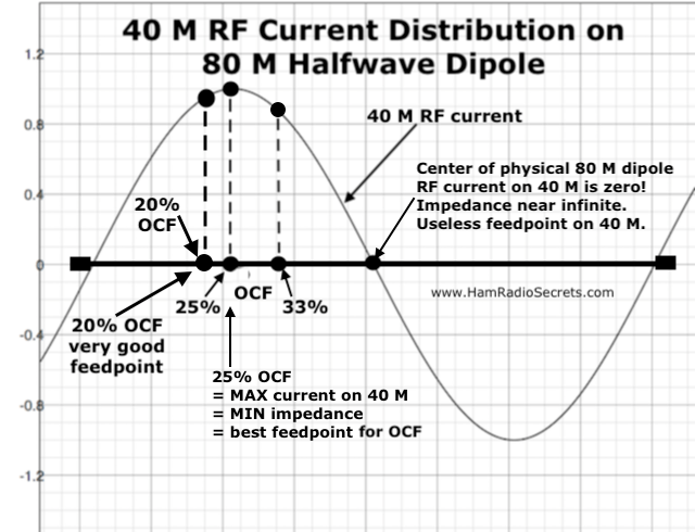
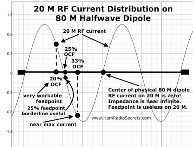
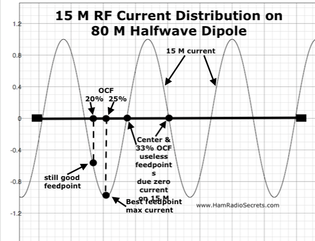
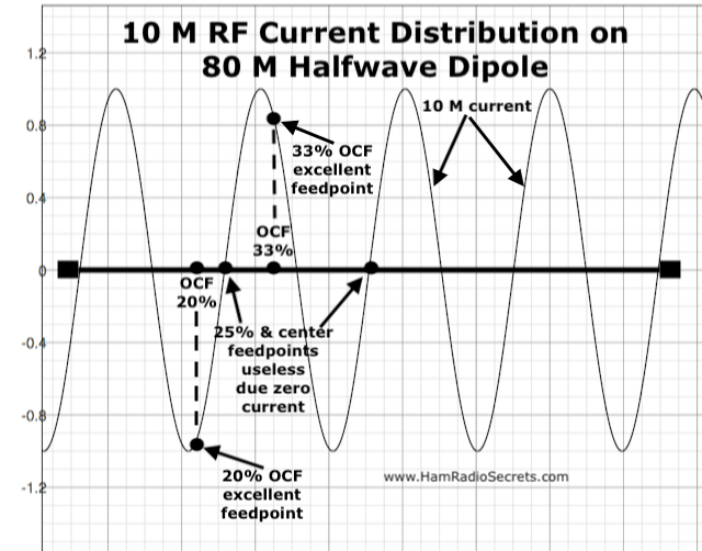
Let's find out by examining different offset feedpoints on an 80 M half-wave dipole for each amateur radio HF band. Offsets of 33%, 25% and 20% will be illustrated.
Off-Center-Fed Dipole
(OCF) Graphs
Even Harmonics of (f0) 3.5 MHZ (80 M Band)
Second harmonic (2xf0) = 40 M Band (7 MHz)
Fourth harmonic (4xf0) = 20 M Band (14 MHz)
Sixth harmonic (6xf0) = 15 M Band (21 MHz)
Eighth harmonic (8xf0) = 10 M Band (28 MHz)
Odd Harmonics of (f0) 3.5 MHZ (80 M Band)
The Third Harmonic (3xf0) of 3.5 MHz
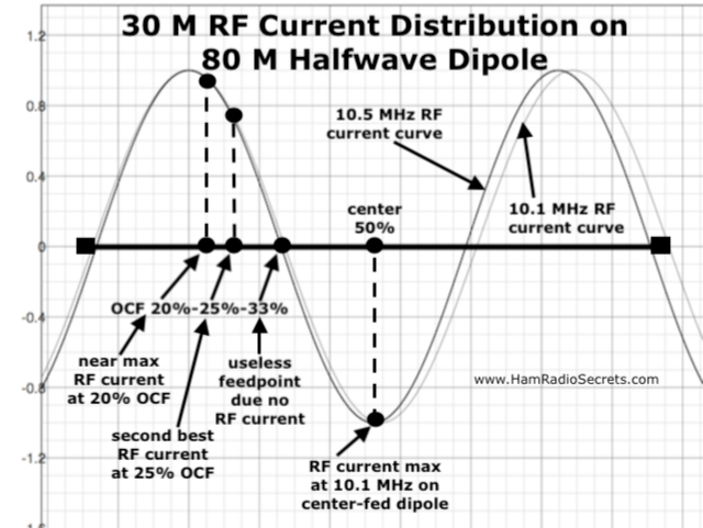
The third harmonic of 3.5 MHz (3xf0) is 10.5 MHz but our amateur radio 30 M band allocation is a shade lower in frequency at 10.1 - 10.15 MHz. The 10.1 MHz current curve is shown in lighter grey on the graph, a shade to the right of the 10.5 MHz (3xf0) curve. As you can see on the graph, the antenna is *physically* a little too short (3.96%) to fully accommodate three complete half waves at 10.1 MHz.
The Fifth Harmonic (5xf0) of 3.5 MHz
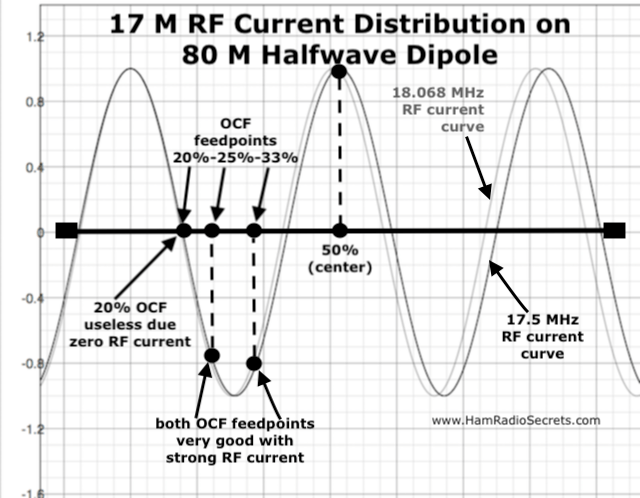
The fifth harmonic of 3.5 MHz (5xf0) is 17.5 MHz but our amateur radio 17 M band allocation is a shade higher in frequency at 18.068 MHz. The 18.068 MHz current curve is shown in lighter grey on the graph, a shade to the left of the 17.5 MHz (5xf0) curve. As you can see on the graph, the antenna is *physically* a little too long (3.14%) at 18.068 MHz.
The Seventh Harmonic (7xf0) of 3.5 MHz
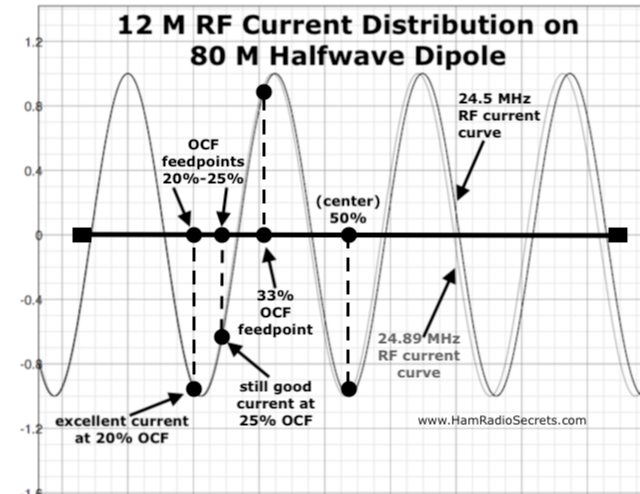
The seventh harmonic of 3.5 MHz (7xf0) is 24.5 MHz but our amateur radio 12 M band allocation is a shade higher in frequency at 24.89 MHz. The 24.89 MHz current curve is shown in lighter grey on the graph, a shade to the left of the 24.5 MHz (7xf0) curve. As you can see on the graph, the antenna is *physically* a little too long (1.57%) at 24.89 MHz.
Use Of An 80 M Off-Center-Fed Dipole On A Non-Harmonic Frequency
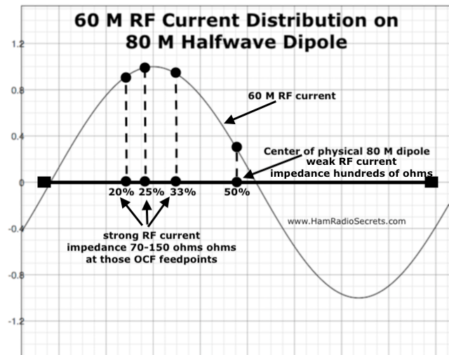
The 60 M band (5.3-5.4 MHz) is higher in frequency than the 80 M band but not quite twice (even harmonic) of 3.5 MHz. Therefore a full wave at 5.3 MHz does not quite fit within an 80 M dipole. In other words, the 80 M dipole is *physically* too short to fully accommodate two complete half-waves at 5.3 MHz. Nonetheless, the 80 M dipole - fed off-centre - will definitely be suitable for use on 60 M.
How About a 160-Meter
Off-Center-Fed Dipole?
Will a 160-meter OCF dipole work as a multiband antenna?
First, I do not have enough horizontal space to experiment with a full-size 160-meter horizontal dipole. Therefore, I have never tried.
As for modeling one, I admit that I have never bothered to master modeling antennas with EZNEC. Modeling only gives theoretical ball park values anyway, because we are never quite sure of the many physical variables that make up the antenna's operational environment. Reality is always different, sometimes appreciably.
Nevertheless, let’s look at the problem pragmatically.
If a resonant 160 m dipole is fed at its center (50%) maximum current is available there. The dipole will also be resonant on odd multiples of its fundamental frequency of resonance.
Let's look at the frequencies where a 1.8 MHz half-wave dipole will also be resonant.
|
F |
fx3 |
fx5 |
fx7 |
fx9 |
fx11 |
fx13 |
fx15 |
fx17 |
|
1.8 |
5.4 |
9 |
12.6 |
16.2 |
19.8 |
23.4 |
27 |
30.6 |
|
fx1 |
~60 m |
BLO |
BLO |
BLO |
BLO |
BLO |
~CB! |
ABV |
The first thing we notice is that, except for 60 meters, the 160-meter band is not harmonically related to higher frequency ham bands!
Note also that, again except for 60 meters, resonant frequencies (max peaks of current) skip over the 80 m and 40 m bands entirely, then occur below higher frequency ham bands, except for ten meters where it's resonant above.
This means that, if we feed a 160 m half-wave dipole at its center, we already get less than optimum current on higher frequency bands by being off frequency on all ham bands above 40 meters.
OK. That's for basic theory.
Now in practice...
To start with, the 160 m half-wave dipole will likely be installed too low in terms of above ground which will pull its resonant frequency down. The length of wire, obtained with the formula (468 / f), will have to be trimmed to bring its frequency of resonance back up within the 160 m band.
By further removing the feed point away from the center of the dipole, we further reduce the amount of current on resonant frequencies... which are, themselves, already off frequency on all ham bands!
In light of the above, where positioning the off-center-fed dipole feed point is concerned, your guess is as good as mine. Feeding the 160 m dipole at 22.5% from one end is as good a starting point as any to start experimenting with, I guess!
Other factors influencing resonant frequencies (and amount of available current):
- Height of antenna (in terms of ) above ground, especially for 160 m.
- Dielectric constant and conductivity of the ground below the antenna.
- Wire resistance becomes a factor (drags down resonant frequencies) as we try to use the antenna at higher frequencies.
Considering the above, using a 160 m half-wave off-center-fed dipole (OCFD) to also cover higher frequency ham bands is just not feasible.
Mind you, feeding it with open wire line and using a wide range 'L'
network tuner, you might get it to "sorta work" on most HF bands above
1.8 MHz, but how efficient and effective will such a contraption be?
In
any case, avoid using a 'T' network tuner with any OCF dipole antenna
(or any other type of antenna for that matter!). They are simply much too 'lossy'
(dissipate RF power as heat in the coil when SWR is too high). See this article for more information on tuners.
Preliminary Conclusions
After examining all the graphs above, we can see that:
- A 33% offset feedpoint will not allow use of the 80 M OCFD on 30 M and 15 M where the RF current is zero, resulting in unworkable impedances in the thousands of ohms.
- A 25% offset feedpoint will not allow use of the 80 M OCFD on 20 M and 10M for the same reason.
- A 20% offset feedpoint will not allow use of the 80 M OCFD on the 17 M band due to lack of enough RF current.
But a closer look at each graph indicates - at least in theory - that feeding an 80 M half-wave off-center-fed dipole somewhere between the 20% and 25% offsets would make it usable on all HF ham bands (except 160 M), because there would be enough RF current in all cases.
Of course, any feedpoint where the RF current will be less than maximum - while still greater than zero - will exhibit higher impedance than the theoretical 70-72 ohms of a center-fed half-wave dipole in free space. An open wire high impedance feed line is highly recommended.
That's why I chose to feed my OCFD with 450 ohm ladder line:
- its characteristic impedance will likely be closer to the higher impedances of an off-centre fed dipole than coaxial feed line;
- the ladder line's extremely low loss characteristic means that even high SWR values will result in negligible losses. In plain language, I couldn't care less about the OCFD's impedance on the frequency bands I wish to use the antenna on.
Of course, in practice, height above ground, ground conductivity and the presence of structures within a half wavelength of the antenna will have an influence on the impedance of any feedpoint one might choose.
BALUN OR UNUN?
Must I point out here that an off-center-fed dipole antenna is inherently an unbalanced antenna!
Therefore, using a balun - a BALanced to UNbalanced transformer - with such an antenna caters more to popular misconceptions than to common sense. A UNUN - at the off-center-fed dipole feedpoint - would be much more appropriate for those who absolutely insist on using lossy coax transmission line with an antenna. A UNUN would, at least, serve to (somewhat) prevent RF currents from travelling down the outer shield of a coaxial feed line... and interfere with equipment in the shack and/or in the house... or a neighbour's house!
On the other hand, a 9:1 UNUN would make more sense at the transceiver end of the 450 ohm transmission line... as a necessary attempt to match with the 50 ohm RF terminal of a transceiver while also serving as a RF choke.
Admittedly, the complex impedances which will appear at the end of the 450 ohm transmission line cannot be transformed into a purely resistive 50 ohm impedance with a UNUN.
Therefore, it will still be necessary to use an antenna tuner to transform the complex impedances to something within the range of impedances that the transceiver can safely work with.
A further argument in favor of 450 ohm ladder line is that a low-loss transmission line is an absolute *must* in receive mode. When I'm working QRP, I need the few microvolts of RF "juice", that my off-center-fed dipole antenna has managed to catch, to reach my receiver instead of being dissipated as heat along a coaxial transmission line.
Generic 450 ohm ladder line has a matched loss of 0.08 dB/100 feet at 10 MHz... while 100 feet of RG-8X coax will squander 0.7-1.0 dB at the same frequency... an order of magnitude more than ladder line! I rest my case here on transmission line efficiency.
To avoid the inevitable (small) RF losses caused by a UNUN between the ladder line and the final relatively short length of coaxial line entering the radio room, I chose not to use one.
Instead, I chose to connect the ladder line directly to the coax using a homemade weatherproofed junction box outside the house. Then, to prevent RF (travelling along the coax shield of the lead-in) from entering the shack and crating havoc, I use snap-on ferrite RF chokes on the coax before it enters the house.
For the snap-on ferrite RF chokes, I use Palomar Engineers products. They recommend:
"For 1/4” cables use five FSB31-1/4 split beads for 80-10 meters (3-30 mHz)".
Reference:
https://palomar-engineers.com/ferrite-products/Snap-On-Mix-31-RFI-Range-1-300-MHz-c21480229
Best placement for the ferrite snap-on RF chokes would be on the RG-8X coax transmission line, just before it enters the radio room from outside.
But... before you spend any money of ferrite chokes, you could simply try a homemade RF choke by winding a portion of the RG-8X transmission line - about 10 turns on a plastic form, as I describe on this other page of my website:
https://www.hamradiosecrets.com/160-meter-antenna.html
I leave the task of matching the complex impedances - appearing at the XCVR end of the coaxial transmission line - to my LDG AT-600PRO (L-network) automatic tuner.
Summary
In light of the above, I believe that:
- An 80 M half-wave off-center-fed dipole, with a feedpoint at about a 22.5% offset from one end, will give access to all HF bands from 80 meters up to 10 meters.
- The best transmission line to use in such a case is 450 ohm ladder line for its extremely low loss characteristic.
- As you may have guessed by now... the ladder line will radiate! The radiated RF energy will be vertically polarized, with a low angle of radiation, which is good for DX!
- The ladder line should be connected directly to the coax lead-in, using a weatherproofed box outside the shack.
- Think of the OCFD as a end-fed antenna with a small counterpoise (or a vertical lying on its side ;-)
I connect the shield of the coax to the short leg of the off-center-fed dipole.
I
honestly do not know if this is preferable as I have not done any
comparative testing of the resulting radiation patterns. I just feel it
makes more sense.
- Snap-on ferrite chokes must be installed on the coax lead-in to prevent parasitic RF currents from entering the house and interfering with equipment in the radio room, and other electronic devices elsewhere in the house and a neighbour's house.
- A good quality wide range antenna system tuner should be able to handle the complex impedances which will inevitably appear at the XCVR end of the transmission line coming down from an 80 M half-wave off-center-fed dipole being used as a multiband HF antenna.
73 de VE2DPE
Claude Jollet
104-30 avenue des Berges,
Notre-Dame-des-Prairies, Québec, Canada J6E 1M9
QTH Locator: FN36gb
Disclosure
If
you make a purchase via a link on this site, I may receive a small
commission on the transaction, at no extra cost to you. Thank you!
(One word queries work best)
HF Antennas
Section
Contents
VHF/UHF Antennas
FOUND THIS
SITE
USEFUL?
VE2DPE
Is a member
in good standing
of

Also a proud member of an international community of solopreneurs
using SoloBuildIt!
(SBI!)
to promote my self-published eBooks
since 2005.
See my review
of this unique product for online businesses.
CQ CQ CQ
If you have a question, a comment or a topic you would like me to cover, please do not hesitate to ask here.
