Ham Radio Projects
In my view, nothing beats ham radio projects in terms of personal satisfaction, not to mention getting more for your hard earned money!
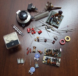 Ham Radio Projects Components
More often than not, I will prefer home-brewed ham radio accessories to their commercially made equivalents.
Sometimes there is no commercial equivalent to be found at all!
I describe one such accessory project below. It's one of my favorite projects to date: it's simple, useful and unique.
The commercially made amateur radio accessories are too often designed
and manufactured with one eye glued on profits - and the other on
marketing considerations!
The inevitable compromises that
manufacturers make to fatten their "bottom line" rarely coincide
completely with the ones you would have made, had you designed and hand
crafted the equivalent accessory yourself.
Commercially made
accessories often have to please more than one type of customer. You end
up being offered a "one-size-fits-all" piece of equipment ... and
paying - in part - for features you don't need.
Building some of your own ham radio accessories - as ham radio projects - means that you will only spend your money on the subset of functionalities and features you really need!
Start home brewing a little something for the shack! You might have to review your radio theory. All the better! Start with a small feasible project. Build your abilities and confidence with each subsequent project.
In doing so, you will make operating your station easier and greatly enhance your overall enjoyment of ham radio.
Remember! You stand to save a fair bit of money by home brewing the amateur radio accessories you need. Some examples of feasible projects are:
- antennas
- antenna system impedance matching devices (antenna tuners a.k.a "Transmatch")
- simple circuits like receiver front-end protection from strong RF signals (see article below)
- QRP equipment (transmitters, receivers, power supplies, low power "Transmatch", QRP SWR meter, etc.)
SDR Receiver Protection Project
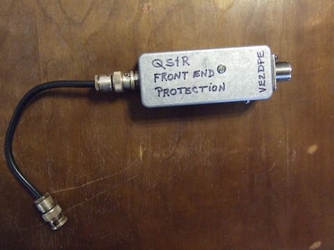 My completed project
This article is about what I consider to be an essential ham radio accessory for which I could not find a suitable commercially made substitute.
Among all the ham radio projects that I have waiting on my drawing board, I find that this one fits the goal in the preceding paragraph perfectly.
The Project's Purpose
I needed to protect the sensitive front end of my QS1R SDR receiver when transmitting with my IC-7200 barefoot.
Instead of going for a complicated and costly T/R switching arrangement, I decided to build the front-end protection (FEP) circuit based on one recommended by Phil Covington, N8VB, designer and manufacturer of the QS1R Software Defined Receiver (SDR).
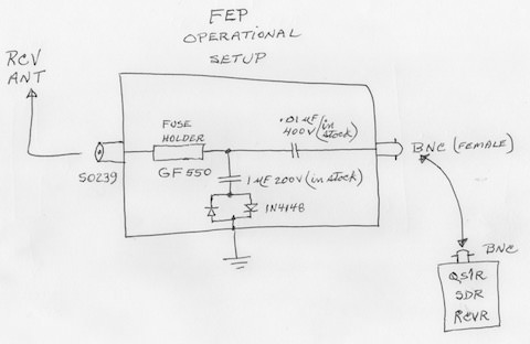 My version of N8VB FEP circuit
This unique ham radio accessory would enable me to always have my SDR receiver monitoring the HF activity while I transmitted on my other antenna with the IC-7200 transceiver.
Not surprisingly, the FEP works as flawlessly as the QS1R SDR it is meant to protect.
FEP: The Setup
I use a separate receive antenna for my QS1R SDR receiver - an end-fed inverted-L 138 foot wire antenna.
The FEP will be inserted between the QS1R SDR and its antenna. It will divert to ground any excessive RF voltage that might otherwise destroy the SDR's sensitive front end.
FEP: Parts Gathering
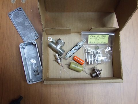 The FEP parts
I bought a small Hammond (1590A) die cast box at a local electronics store. I figured it would be big enough to house the few components of the FEP.
However, I ordered the GF550 fuse lamps online from Mouser Electronics. I bought a half dozen because I knew I could blow one or two either at the testing stage or in full operational situation. I could not find a local supplier for these and did not feel like driving 50 miles to Montreal and back to buy them. It costs considerably less to order online and have them mailed to me. I was right.
I scrounged around in my spare parts for the rest of the components. Here is what I found:
- Two 1N4148 fast switching diodes (Phil N8VB recommends nothing other than 1N4148 for this application!);
- Sprague .1μf/400VDC capacitor (far exceeding the minimum 50VDC recommended);
- 1μf/200VDC capacitor (four times the minimum 50VDC recommended);
- SO-239 UHF bulkhead female jack;
- female 50Ω BNC bulkhead jack;
- a fuse holder for the GF550 fuse lamp.
FEP: Planning The Building Stage
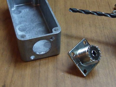 Beginning construction of the FEP.
When I bought the die-cast box, I had not searched for the capacitors in my spare parts yet. When I did find the ones that would suit my purpose, I discovered they were "fat" little critters!
After playing around with different layouts, I finally managed to fit all the components in the box! But it was a close call.
The take-home lesson here is to buy the enclosure last - or make sure the enclosure you have will exceed the space required to house all components.
FEP: The Building Stage
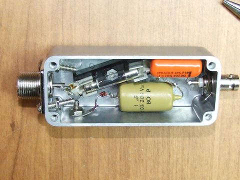 The FEP components neatly squeezed in
Fair warning! First thing to do with parts that you find among your spares for your home-brewed ham radio projects: test them individually! There is nothing more frustrating than to assemble an entire project only to find that one capacitor was shorted or that you had soldered in a dud diode!
I first punched a hole for the SO-239 connector. I used a 15.9mm Greenlee punch that I have had in my tool box for that very purpose since I first started in ham radio back in the early '70s. Then I drilled a hole at the other end of the box for the BNC jack.
After that, with so few parts and enough room to maneuver (relatively speaking) I did not take much time to solder everything together.
FEP: Preliminary Testing
Before putting the FEP into active service under full operational conditions (transmitting while the QS1R is receiving on a separate antenna) I wanted to find out if the FEP would cause some signal loss when inserted between the QS1R and its antenna.
I tuned the QS1R receiver to WWV on 10 MHz and measured the signal on the S-meter of the SDRMAX-V (SDR software). But there was some QSB so I made two other measurements using the closer signals from CHU on 3330 KHz and 7830 KHz.
Then I immediately inserted the FEP in the QS1R's receive line and ran the same tests. I did not see any noticeable signal reduction in the strength of the signal received!
I also ran a few more tests with weak amateur radio signals on all HF ham bands. Ditto. No problem.
So far, so good. I began to get the feeling that this would be my easiest and most satisfying of all my previous ham radio projects.
FEP: The Acid Test
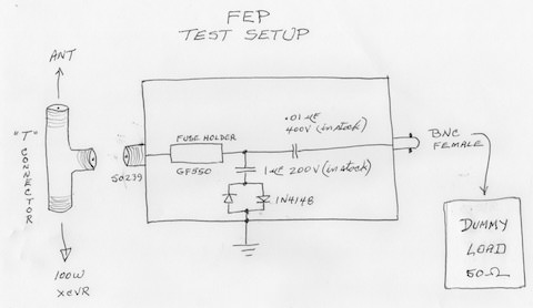 The FEP test setup
Warning! Do not use your receiver as dummy load for this test!
I tested the FEP's sturdiness and capacity to shunt strong RF signals to ground ... in the most violent way at my disposal!
Using a UHF "T" adaptor (SO-239 connectors) I tapped the transmission line between my IC-7200 XCVR and its antenna.
Then I connected the FEP to the tap and a 50 Ohm dummy load to the receiver end of the FEP.
I ran three tests at the following power output levels: 25 watts, 50 watts and 100 watts.
The FEP survived 25 watts and 50 watts, effectively clamping down the excessive RF signals to ground. The GF550 lamp fuse finally burned open at the 100-watt level.
The FEP worked as Phil (N8VB) said it would!
FEP: Operational Test
Finally, I (nervously) ran a full operational test with:
- The IC-7200 connected to its antenna.
- The QS1R SDR receiver connected to its own separate antenna.
Mission accomplished.
The FEP did it's job. It protected my QS1R SDR from harmful RF even when I transmitted a full 100 watts on CW.
I am proud to say that my new home-brewed ham radio accessory (FEP) is now operational.
Barring a component failure in my FEP, my sensitive QS1R SDR is now safely protected against overly strong RF signals.
In light of the preceding paragraph, I assume no responsibility whatsoever for any damages to your equipment as a result of your construction and use of the FEP described above.
"Soft"
Ham Radio Projects
You do not have to limit yourself to hardware projects only.
If you like computer programming, there is an infinite number of ham radio software applications and utilities that you should try to program yourself instead of:
- paying for commercial software that never quite meets your requirements (...)!
- or using free ham radio software that often leaves a lot to be desired!
Try designing and writing some of your own software. There are very good implementations of interpreted "script" languages available for all popular platforms nowadays (Windows, Mac OS X, Linux).
I personally
like Perl and Python interpreted languages. In any case, choose the programming language you are most comfortable with and give it a whirl!
You will find comprehensive lists of resources suitable for learning Perl and Python languages at the following URLs:
Perl: www.whoishostingthis.com/resources/perl/.
Python: www.whoishostingthis.com/resources/python/.
My Favorite
Amateur Radio Projects
One often overlooked opportunity, among all the ham radio projects you would like to take on, is the so-called "antenna tuner".
My pet peeve here is with the embarrassing inefficiency of most so-called "antenna tuners". By the way, I believe they should be more appropriately called "antenna system impedance matching devices"! In fact, that's where the well known name "Transmatch" comes from!
They are meant to ensure that the antenna system's (transmission line and antenna together) overall impedance matches that of the transceiver, transmitter or receiver.
The reason such matching is so desirable is that maximum RF energy is transferred when the ham radio's nominal terminal impedance matches the antenna system's impedance - be it on transmit or receive.
Most commercially made "antenna tuners" you find nowadays are highly inefficient (lossy) "T" matching networks.
Fortunately, there are exceptions. A few antenna system matching devices are made using "L" networks (i.e. Palstar and LDG). These are more expensive but so much more efficient and effective in transferring RF energy with the least amount of loss. (See this other article for more in depth discussion on impedance matching networks).
"L" network tuners usually require large high-voltage air variable capacitors. You can sometimes find used ones at hamfests. On the other hand, you can of course buy them new from:
- Palstar.com
- RFParts.com
- OrenElliottProducts.com
Here's wishing you many hours of pleasure in planning, designing, building and using the finished products of your ham radio projects!
73 de VE2DPE
Claude Jollet
104-30 avenue des Berges,
Notre-Dame-des-Prairies, Québec, Canada J6E 1M9
QTH Locator: FN36gb
Disclosure
If
you make a purchase via a link on this site, I may receive a small
commission on the transaction, at no extra cost to you. Thank you!
(One word queries work best)
EQUIPMENT
Section
Contents
FOUND THIS
SITE
USEFUL?
VE2DPE
Is a member
in good standing
of

Also a proud member of an international community of solopreneurs
using SoloBuildIt!
(SBI!)
to promote my self-published eBooks
since 2005.
See my review
of this unique product for online businesses.
CQ CQ CQ
If you have a question, a comment or a topic you would like me to cover, please do not hesitate to ask here.


