The Sloper Antenna Explained
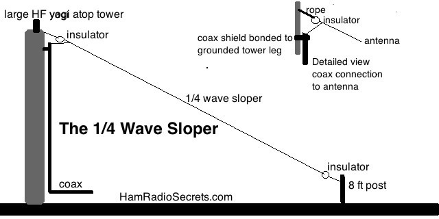
The classic sloper antenna is a top-fed 1/4 wave vertical antenna sloping down and away from a tower. The sloper's feed point is anchored high above ground near the top of the tower on which sits a grounded HF yagi beam antenna. The yagi plays the role of a ground plane, while the tower plays the double role of reflector and grounding "rod".
I have found, from experience, that the performance of any grounded quarter-wave HF antenna, be it a bottom-fed vertical or top-fed sloper - depends heavily on the soil's conductivity and dielectric constant below it.
To illustrate, using extremes, the classic sloper antenna will perform
- extremely well over sea water
- very well over marshy soil
- very poorly over dry sandy ground.
Furthermore, the properties of the soil will vary from season to season, if you live in an area where there are seasons, of course!
This means that the performance of classic sloper antennas will range from excellent to mediocre, depending on geographical location and season.
The classic sloper antenna is NOT an easily reproducible antenna system. Some installations may produce excellent results, while others will not - for often inexplicable reasons.
Please note: the antennas described here are fed with RG-58X coax. I also use an LDG automatic tuner between the antenna transmission line and my XCVR.
Therefore, my preference always goes to balanced antennas such as dipoles or loops. The effects of the quality of the soil below, even if it does play a role, are not as critical to the performance of such antennas.
So, I will concentrate this article on sloping balanced antennas and various ways of installing them.
The Quarter-Wave Sloper Antenna
With Counterpoise (QWSWC)
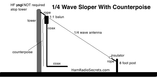
The QWSWC is a somewhat unbalanced half-wave dipole. Like with a classic dipole, its feed point should be as high as you can install it.
The 1/4 wave section slopes down from the feed point. The other section - the counterpoise - can drop down vertically or angle away from the antenna and it's feedpoint. Note that the counterpoise of a 40-meter band sloper antenna will not reach the ground if the tower is 48 feet tall. Keep it at least 6 inches to a foot away from the tower leg.
The technique that I use to obtain minimum SWR is to tightly fold the end of the counterpoise wire back on itself - a 5-6 inches at a time - until I reach an SWR minimum.
If your antenna is cut for the 80 meter band, its counterpoise will be
longer than a 48 foot tower. A portion of it can run on the ground - in
which case the antenna wire must be insulated - or run parallel to the
ground.
Because of this, I suggest that the counterpoise be 1-2%
longer than the 1/4 wave section. It can be trimmed a little at a time
until the SWR dips to a minimum.
Do not expect 1:1 SWR on the base frequency of this antenna. An antenna tuner is required.
Running part of the counterpoise above and parallel to the ground requires two additional 7-8 feet tall supports: one straight down below the antenna feed point, the other far enough away that the counterpoise section can run parallel to ground level. It could be sloping down too.
The supports should be at least 7-8 feet tall for safety reasons. I use 8 foot posts to be on the safe side.
We must prevent people from coming in contact with the antenna when in transmitting mode.
High RF voltages
can cause serious injuries, even death.
Admittedly, this type of configuration (see image above) is not far from that of the inverted "V".
However, the radiation pattern of the QWSWC will differ from that of the classic inverted "V".
The
counterpoise section of the quarter-wave sloper described here will act - in part - like a reflector to the 1/4 wave
section sloping down. The angle separating the two sections will be less
than 90 degrees. There will be interaction between the two sections -
whereas it is not (as much) the case of an inverted "V" with an angle of 90
degrees or more between the two legs at the apex.
I should
mention that - because of its vertical portion - the QWSWC will have a
tendency to pick up a little more QRN and electrical noise interference
than the classic inverted "V". But, in my opinion, that's a small price
to pay for the advantage of being able to put up a relatively balanced
antenna in less space that an inverted "V" would require.
This
antenna can be fed with 50 ohm coaxial cable, via a 1:1 balun.
However, try to avoid running the coaxial cable down vertically from the antenna's feed point, if you can. The coax would then be parallel to the counterpoise section of the antenna and its shield would pick up a fair amount of RF that you will have to (try to) stop cold before the coax enters the shack.
In fact, even if the coax runs down at an angle to the shack, an RF choke (see this page) will help prevent your antenna tuner from behaving erratically. Without an RF choke, the tuner may have a hard time cancelling out the SWR present on the line.
The Multiband Version
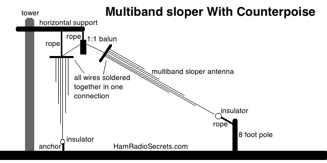
I have used 300 ohm twin-lead and 450 ohm ladder line to build multiband versions of the 1/4 wave sloper antenna with counterpoise in past experiments. This technique gives better results than trying to force a single-band antenna system to work on higher bands, using an antenna tuner.
The antenna wire for the 15 meter band (21 MHz) can be omitted because the base antenna on 40 meters (7 MHz) will cover it on its third harmonic.
Therefore, using twin-lead or ladder line, i was able to construct a multiband antenna covering seven HF bands:
40 meters (7 MHz)
30 meters (10.1)
20 meters (14 MHz)
17 meters (18.068 MHz)
15 meters (third harmonic of 40 meter band)
12 meters (24.89 MHz)
10 meters (28 or 29 MHz depending on preferences)
Just prune the counterpoise of the base frequency (7.0 MHz) to obtain minimum SWR. Do not bother pruning the counterpoise wires for each of the higher bands. Your antenna tuner should easily take care of the SWR.
The Half-Wave Dipole
Sloper Antenna (HWDSA)
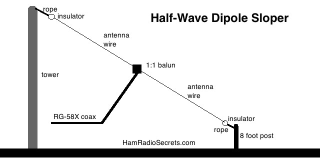 Half-wave dipole sloper antenna (drawing not to scale)
A half-wavelength dipole antenna will give better results than the quarter-wave (single band) sloper described above.
The drawback is that you need more horizontal space!
A dipole for the 40 meter band - sloping down from a 48 foot tower or from the roof of a three story building - will require that the other support post (say 8 feet tall) be located at least 53 feet away from the tower.
On the other hand, the quarter-wave sloper for 40 meters would require that a similar end-support post be located only about 23 feet from the tower!
If you have the space, install a sloping dipole. It will be more efficient (much less lossy) than the classic quarter-wave sloper antenna (described at the beginning of this article) and, thus, will be more effective.
Feed the HWDSA with RG-58X coax via a 1:1 balun. Try to have the coax come away from the dipole at a 90 degree angle if you can. The sloping dipole will induce RF currents on the shield of the coax. You will have to install an RF choke (see this page) to prevent this unwanted RF from entering the radio room.
The Full Wavelength Loop
Sloper Antenna (FWLSA)
Here is a sloper with a twist. It's my favorite sloper-type antenna and it's the one I am using now.
I admit that I am very fortunate to have tall trees conveniently located just the right distance away from my house!
A full wavelength loop antenna, when installed vertically, radiates
perpendicularly (broadside) to the plane of the antenna, with a deep null
in the plane of the antenna.
However, a loop antenna for any
band of frequencies below 20 meters requires a very special (spacious!)
environment including tall, very tall supports!
But, what if ...
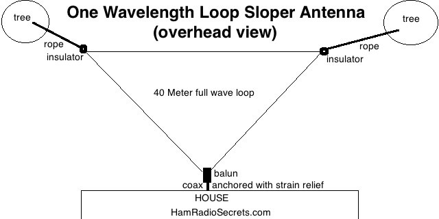
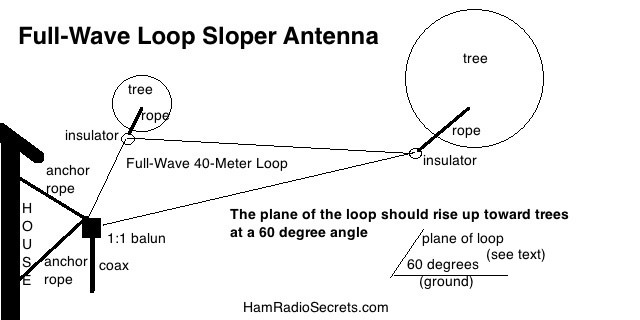
Here is how I installed one such antenna at my QTH. I chose to build a loop for the 40 meter band with a triangular configuration which would only require three anchor points.
I anchored the loop's feedpoint 8 feet above ground level (for safety) on the outside wall of my house. The outer corners of the loop are tied to two tall maple trees using insulators and Dacron rope. The antenna slopes up toward the trees. The angle "A" - between the plane of the antenna and ground - is about 60 degrees.
The overall length of wire required for the loop is found by using this formula:
Length (feet) = 1032 / f MHz
Therefore a triangular full wavelength loop antenna for 40 meters will require about 145 feet of wire. Each side of the triangle will be about 48.5 feet long.
If the loop antenna were to be installed horizontally, the far corners of the triangular loop would be about 42 feet away from the feed point. But, since my loop antenna is installed at a 60 degree angle from the ground (in my example)
- the far corners of the triangle will only be about 21 feet away from the house (baseline measured on the ground from the loop feed point to under the horizontal portion between the far corners of the triangle).
- The far corners will be about 36.4 feet above ground - a very acceptable minimum height for a 40 meter antenna.
In other words. the above antenna will fit over an area of about 22-25 feet deep by about 50 feet wide (as measured on the ground).
The above measurements require a bit of trigonometry calculations to plan the antenna size (frequency band) that will fit within your specific environment. Otherwise, you will have to use the old trial & error method ... which is perhaps more fun in the end!
With the above dimensions, the loop will be close to resonance at 7.1 MHz. Its radiation resistance will be in the neighborhood of 120 ohms. A 2:1 balun should be used to connect 52 ohm coax to the loop, but a 1:1 balun should do (because you should be using an antenna system tuner anyway).
The loop's dimensions are larger than a 1/2 wavelength dipole.
Thus, its radiation efficiency is high.
Speaking of radiation, its major lobe will hit the ionosphere at an
angle of about 30 degrees which is pretty good for DX. Some minor lobes
will favor NVIS (Near Vertical Incidence Skywave), which is desirable
for local contacts out to about 500-600 miles.
As no antenna will
let you have it all, most contacts will lie in the direction opposite
the slope of the antenna.
In other words. if the antenna is installed on
the West side of your house, sloping up westward toward the trees (or
some other tall supports), most of yours contacts will lie toward the
east.
Compared to a half-wave dipole sloper, I find that the loop
sloper is a better receiving antenna than a dipole. It seems, from
experience, that the full-wave loop captures more microvolts of signals
than the dipole.
On the other hand, a sloping dipole would cover
two to three directions instead of just the one for the sloping loop.
Your choice.
Full-wave Loop Sloper Antenna
Bonus Band Coverage
The 40 meter (7.1 MHZ) full-wave loop antenna will also be resonant on:
20 meters ( +/- 14.2 MHz)
15 meters ( +/- 21.3 MHz)
10 meters ( +/- 28.4 MHz)
The
sloping loop's radiation pattern will become split in an ever
increasing number of side lobes (of lesser amplitude) as you use the
antenna on higher frequency bands. Nonetheless, you will be pleased with
the results.
Your antenna tuner should have no trouble making the loop work on any part of these "extra" bands!
For
best results on other bands than the one the antenna is cut for, I
would suggest installing counterpoise wires for each higher band you
want to use it on.
- Connect these wires to the shield side of the coax at the
base of the balun.
- Alternatively, you could attach them to the ground lug of your antenna tuner.
Performance Results
My full-wave triangular loop sloper favors amateur radio stations south of me. As a result, I have the United States and South America in my sights, even when propagation conditions are poor.
I have another general purpose antenna to cover Eastern Canada and Europe - an inverted "L" end-fed wire - which I can use on 160 meters to 10 meters, using an LDG automatic antenna tuner.
But my loop sloper is a blast to work with! It packs a lot more punch ... albeit only southward. It's also quieter on receive (picks up less QRN).
I'll admit. I'm spoiled.
If you have the space, spoil yourself too!
73 de VE2DPE
Claude Jollet
104-30 avenue des Berges,
Notre-Dame-des-Prairies, Québec, Canada J6E 1M9
QTH Locator: FN36gb
Disclosure
If
you make a purchase via a link on this site, I may receive a small
commission on the transaction, at no extra cost to you. Thank you!
(One word queries work best)
HF Antennas
Section
Contents
VHF/UHF Antennas
FOUND THIS
SITE
USEFUL?
VE2DPE
Is a member
in good standing
of

Also a proud member of an international community of solopreneurs
using SoloBuildIt!
(SBI!)
to promote my self-published eBooks
since 2005.
See my review
of this unique product for online businesses.
CQ CQ CQ
If you have a question, a comment or a topic you would like me to cover, please do not hesitate to ask here.
