Ham Radio Dipole
Basic Introduction
The ham radio dipole is called a half-wave antenna because its length corresponds to an electrical half wave at the frequency for which it is intended.
This Page Covers
1. Antenna System
2. Dipole Formula
3. Resonant Length
4. Transmission Line
5. Dipole Hardware
The classic dipole is also called a balanced antenna because it is "fed" at its exact center.
The half-wave ham radio dipole is also the most common antenna used by amateur radio operators throughout the world.
Why Is The Dipole So Popular?
Because it is an inexpensive, yet effective, antenna, especially if you build it yourself using wire, insulators and rope that you already have in your (or a friend's) "junk box" of spare parts!
A Picture Is Worth . . .
Here is a simplified illustration of the classic dipole antenna.

The characteristic impedance of a half wave dipole is around 73 ohms.
However, if the horizontal dipole is between 0.1 and 0.2 wavelength above ground, its impedance will be somewhat lower and closer to 50 ohms ... the characteristic impedance of commonly used coaxial transmission line such as RG-8, RG-8X and RG-58.
As a bonus, the impedance will remain low at odd harmonic multiples of the basic frequency! Yes, you can operate a 40 meter (7 MHz) dipole on 15 meters (21 MHz) too. A two-for-one antenna!
The Antenna "System"
Keep in mind that the antenna is only part of a coherent system! An antenna system is composed of...
- The antenna (the radiating and receiving portion).
- The transmission line (carrying the RF energy between the antenna and the transceiver).
- The impedance matching unit between the transmission line and the transceiver.
Ham Radio Dipole
Formula
The formula to calculate the (approximate) overall physical length of a dipole is:
Length (meters) = 142.58 / frequency (MHz)
Length (feet) = 468 / frequency (MHz)
The length of wire given by the formula is cut in half to make both sides of the dipole.
The above formula gives an approximate result because the length at the desired resonant frequency is affected by its operating environment conditions, such as...
- the antenna height above ground,
- the conductivity of the ground itself,
- the proximity of metal structures and other objects.
Ham Radio Dipole
Resonant Length
Most dipoles will require a little "pruning" to resonate at the desired frequency. I recommend that you...
- Cut your dipole wire some 2-3% longer than the length given by the formula.
- Make a note of the length obtained in step 1.
- Raise the dipole to its operating height.
- Measure the SWR at several frequencies within the intended frequency band. (Use only a few watts and pick a quiet time on the band to make your tests).
- Note the frequency (F_min) at which minimum SWR is obtained.
- Multiply (F_min) by the antenna length recorded in step 2.
- Divide the result of the above multiplication by the desired frequency of operation, to obtain the final length.
- Trim both ends of the dipole down to the final length obtained in step 7.
Ham Radio Dipole
Transmission Line
You can feed your dipole with coax, as already mentioned above.
However, coaxial cable is unbalanced! When feeding a balanced load, such as a dipole, with an unbalanced transmission line, the antenna will induce RF currents on the outer shield of the coax.
These unwanted RF currents spell nothing but trouble, not the least of which are RFI (radio frequency interference) and stray RF in the shack to play havoc with your computer or other delicate electronic devices!
Fortunately, you can prevent these unwanted RF currents from traveling back on the outer shield of your coaxial transmission line ... with a RF choke.
RF Choke Balun
To make a choke balun, all you need to do is wind a portion of the coaxial transmission line to form a coil.
A choke balun made of coax is most effective when a single layer is close-wound on a form, such as 4in. plastic drain pipe or 6in. "schedule 40" PVC pipe.
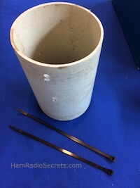
A Prototype Coax RF Choke
- The prototype uses a short length of 4 in. diameter PVC pipe (4 3/16 outside diameter).
- One turn of RG8X will be 14 inches long on the PVC form.
- Therefore 8 turns will require 9.3333 feet of coax.
In other words, the RF choke will take up around 9.5 feet of the RG8X coaxial transmission line feeding your ham radio dipole. Plan that extra length into your overall coaxial line between your antenna and your transmitter or antenna tuner.
Ideally, the coaxial line should *not* be cut to allow the RF choke to be inserted in the coaxial run.
Otherwise, if you cut your transmission line to insert the RF choke, you will need two weatherproofed junction boxes, each with a SO-239. The RF choke will also have to be fitted with a PL-259 at each end. The connections will have to be carefully weatherproofed with Coax-Seal (TM).
Building Instructions

To illustrate, here is how I built an eight-turn RF choke for use on 20 meters. The tube does not have to be as long as in the photo. It's a prototype.
1. First, 8 turns of RG8X will become a 2 3/8 in. wide coil on the 4 in. PVC tube that I use as a form.
Therefore, for the final version, a three-inch-long PVC tube would be more than long enough to hold the coax coil.
2. You will need to drill holes for the Tiewraps(tm) which will hold the coax coil in place on the tube: mark the position of the holes at each end of the coil.
(see photo of marked positions and of drilled holes and of drilled tube with Tiewraps(tm) on the table)

3. Tie down one end of the coax coil. Then wind the coax on the form.
Tip: The end of the coax section being wound on the PVC form should be loose (unconnected). If not, it will end up full of twists! ;)
4. Tie down the other end of the eight-turn coil with a Tiewrap(tm).
(see 2 photos of the finished prototype - one with uncut Tiewraps(tm) and one with cut Tiewraps(tm).)


The table below lists values for each HF amateur band. Form size and number of turns are optimized for each band.
Single Band RF Chokes
(most effective)
|
Band |
Form |
Coax |
Coax |
|
160 |
6 in. |
8 turns |
5-6 turns |
I recommend one choke near your ham radio dipole antenna feed point, and another one about a quarter wavelength down the line, before the coax enters your radio shack.
If you intend to use your dipole on its odd harmonics (more than one band) then use the following table to construct your RF chokes.
Multi-Band RF Chokes
|
Freq. Range (MHz) |
COAX: RG-8, RG-58, RG-59, RG-8X, RG-213 |
|
3.5 - 30 |
3.05 m. (10 ft.), 7 turns |
Ferrite RF Chokes
If you do not want to bother building RF chokes with coax, you could use ferrite RF chokes instead. (see photos)
 Opened ferrite RF choke for coax
 Ferrite RF choke closed on coax
Ham Radio Dipole
Hardware
Remember To:
Take your ham radio dipole down at least once a year (twice or more if you have had severe weather) to check for damage (frayed ropes, damaged coaxial shield or connection, etc).
Many kinds of wire, insulators and rope can be pressed into service for a temporary installation.
But for a permanent and safe all-weather installation, here is what I recommend.
Wire
- I use either #14 stranded (7x22) hard-drawn copper wire, for spans less than 45 meters (150 ft.) between stable supports.
- or the very strong VariFlexTM #13, 19 strand, copper-clad steel wire when the antenna needs to be strung between trees.
Insulators
You can use a ceramic "dogbone" as center insulator, but you will have to wrap your coax around it, tie it securely, then split the center conductor and braid to connect to each side of your ham radio dipole ... and seal to prevent water from seeping in the coax! Not exactly the best.
I prefer using a center insulator with a SO-239 ... much easier to seal.
Of course, you could use a 1:1 balun at the dipole feed point. It will serve as center insulator and coax connector. The balun will improve the radiation pattern somewhat ... if your dipole is at least 1/4 wavelength above ground.
Finally, I use #5 Delta CIN ceramic end insulators for their resistance and long leakage path.
Rope
I have had a dipole strung between two large trees for years with (3/16") Mil Spec Dacron® rope. It is still up there! This rope is very strong and abrasion resistant.
73 de VE2DPE
Claude Jollet
7, Rue de la Rive, Notre-Dame-des-Prairies, Québec, Canada J6E 1M9
QTH Locator: FN36gb
Recent Articles
-
Ham Radio - Amateur Radio Fascinating Secrets
Apr 21, 24 11:06 AM
 Ham radio or amateur radio has fascinated generations. This Web site reveals the secrets behind its enduring popularity and usefulness.
 -
World Amateur Radio Day (WARD)
Apr 17, 24 08:00 PM
April 18, 2024 is World Amateur Radio Day (WARD). Let's all get on the air and make contacts to celebrate this event in style! -
The Ham Radio Infopreneur In You
Apr 01, 24 11:17 AM
Believe it or not, there is an infopreneur (online entrepreneur) in many of us! Often, all you need to make it bloom is proper guidance. You can get it here.


Disclosure
If
you make a purchase via a link on this site, I may receive a small
commission on the transaction, at no extra cost to you. Thank you!
Disclosure
If
you make a purchase via a link on this site, I may receive a small
commission on the transaction, at no extra cost to you. Thank you!
(One word queries work best)
HF Antennas
Section
Contents
VHF/UHF Antennas
FOUND THIS
SITE
USEFUL?
VE2DPE
Is a member
in good standing
of

%20dipole%20antenna.)
%20operator%20VE2DPE%20owner%20of%20www.HamRadioSecrets.com)
Also a proud member of an international community of solopreneurs
using SoloBuildIt!
(SBI!)
to promote my self-published eBooks
since 2005.
See my review
of this unique product for online businesses.
CQ CQ CQ
If you have a question, a comment or a topic you would like me to cover, please do not hesitate to ask here.
Have You Found This Web Site Useful?
Please contribute [ $0.99 ] - [ $3.99 ] - [ $4.99 ] - [ $5.99 ] by way of thanks.
Thank you for your contribution.
You will receive a valuable e-book in return for your generosity.
Solo Build It!
"I'm a solopreneur by design, supported by kindred minds within SBI!"Site Design & Content By Claude Jollet - VE2DPE
Certain text links and image ads on this website contain affiliate links.
I will receive a small commission - at no extra cost to you - if you make a purchase after clicking on them.
For example, as a SiteSell inc. affiliate, I earn from qualifying purchases.

Copyright© 2008-2024 Claude Jollet - HamRadioSecrets.com | All Rights Reserved